| Prev | Gallery 4 - Vic-20 Graphics - page 6 (of 17) |
More Details | Home Page Menu / Back to Overview Page
160 x 176 pixels, produced using a Vic-20 computer.Typical graphics screen output from my Vic-20 computer
|
320 x 352 pixels, produced using a Vic-20 computer.This image used the full 320 x 352 pixel screen of my “BigArt” set of machine code routines, rather than just the small 160 x 176 pixel graphics screen for the first example above. Here, the aspect ratio was set for 1:1 pixels. It looked squashed on the Vic-20 computer screen, but looks fine when viewed back at a ‘normal aspect ratio’ of 1:1. |

|
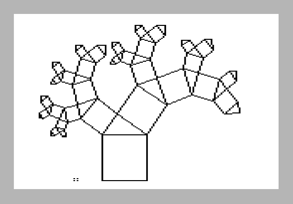
1440 x 2016 printed pixels, produced using a Vic-20 computer.The high resolution prints shown here were all produced using my Vic-20 computer (with some expansion memory added), and my Epson dot-matrix printer. They use specially-written higher resolution graphics machine code routines (to plot pixels, draw lines, and send graphics lines to the printer, etc. on a thin virtual horizontal strip of bitmap graphics screen that was 1440 pixels wide by 48 pixels high), allowing me to produce multiple-line-based images to a maximum resolution of 1440 pixels by 2016 pixels on an A4 piece of paper from the dot-matrix printer. I did this by firstly checking a smaller scaled version of the whole intended drawing on the small 176 x 184 pixel screen of the Vic-20. Even though the screen resolution was much lower than the print resolution, I could at least get an idea of whether the intended drawing was going to fit properly on the printing paper. Note that all of the intended drawings needed to be able to be drawn using lines from scratch from definitions and a specific scaling value. Once I was happy that the intended drawing was going to fit nicely on the printing paper, I then pressed the correct key to change the scaling factors used and send the intended drawing to the printer. A thin virtual horizontal strip of bitmap graphics screen (1440 pixels wide by 48 pixels high, requiring 8,640 bytes of RAM) was defined (and protected) in the computer memory, and this thin strip was initially defined to represent the top 48 pixels of the entire large high resolution image. This thin virtual horizontal strip of graphics screen was then cleared to white, representing a blank strip of white paper. The entire desired large high resolution image was then 'drawn' as black lines over the virtual thin strip (with most of the drawn image not making any changes to any of the computer memory because it lay outside the area of the thin virtual horizontal strip). The thin virtual horizontal strip of bitmap graphics screen was then sent to the printer as 2 graphics lines of printing (24 pixels high each). Once the two graphic lines of printing had finished, the thin virtual horizontal strip of graphics screen was then cleared (back to white), and defined to represent the next 48 pixels of the entire large high resolution image. The entire desired large high resolution image was then 'redrawn' as black lines over the virtual thin strip (with most of the drawn image not making any changes to any of the computer memory because it lay outside the area of the thin virtual horizontal strip). The thin virtual horizontal strip of bitmap graphics screen was then sent to the printer as the next 2 graphics lines of printing. This procedure was repeated until the entire desired large high resolution image was completed (42 sets of 2 graphics lines of printing were required to achieve an image 1440 pixels by 2016 pixels on paper). This high resolution printing graphics technique took some time and management, but I was able to produce some very satisfying results from a computer with quite modest graphics resources. |
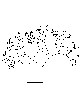
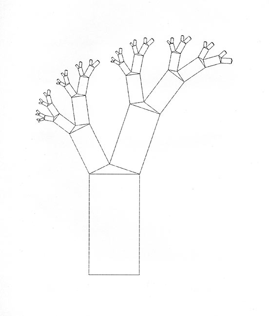
1440 x 2016 printed pixels, produced using a Vic-20 computer.The squares were stretched to become rectangles of similar proportions. This seemed to open up the space between the branches, but didn’t change the angles of the branches. |
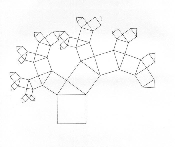
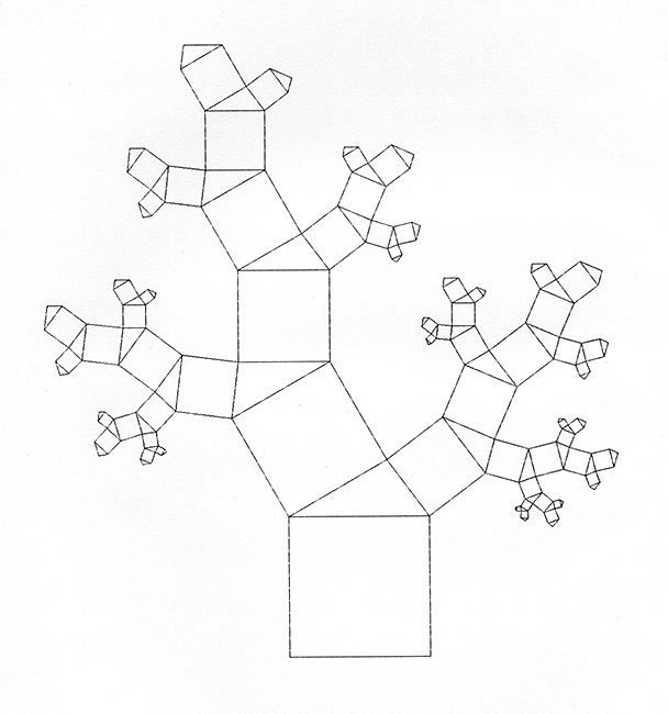
1440 x 2016 printed pixels, produced using a Vic-20 computer.A broccoli type form created by the specific proportions used for constructing the triangles. After doing several different images, I realised that the proportions used for generating the triangles on top of the rectangles determined the way that the branching would occur. One could think of the construction of the square (or rectangle) and triangle as being set by the object’s ‘DNA’. The triangles’ proportions could be set with 2 parameters. In this way, a complex structure was determined by a small number of parameters. I could easily imagine that evolution would favour systems that used fewer parameters. |
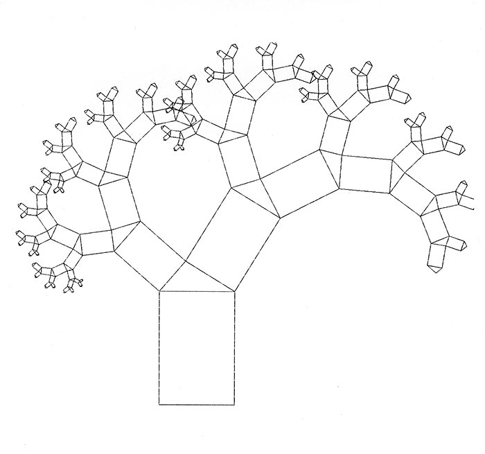
1440 x 2016 printed pixels, produced using a Vic-20 computer.I experimented with switching the orientation of subsequent triangles, and found this produced constructions with quite different characteristics. |
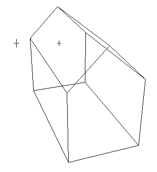
320 x 352 pixels, produced using a Vic-20 computer.I saw a number of computer images in books that suggested computers could produce very good perspective images of 3-dimensional objects positioned in 3-dimensional space. I was keen to experiment with such images. But how did you get a computer to do this? Was I going to be able to do something useful using the Vic-20 computer? At least I had a high resolution screen and fast line drawing routines ready to be used. I found a strategy based on another BASIC program I saw for a different computer. A 3-dimensional ‘model’ was firstly defined by a series of points set up in arrays representing X, Y, and Z coordinates, plus a series of lines between those points (again going into arrays representing the point numbers for the start and the finish for each line). Then depending on how the model was to be viewed, the coordinates of all of the points were all transformed, requiring 3-dimensional rotations and scaling. I wanted the 3-dimensional perspective projection to be accurate, so I decided to try to use my own understanding of 3 dimensional perspective projecting (based on the technical drawing I had done in my school years) to come up with the transformations required. I remember taking quite a bit of time to work out the formulae and trigonometry I was going to use to come up with an accurate perspective projection of a model onto a 2 dimensional plane (a computer screen or printout). Eventually, I came up with my own programming for producing wire frame drawings of models defined in 3-dimensions. I was very proud of the programs and the results I achieved. The simple model of a simplified house was used for testing. It only required having 10 points defined and 15 lines defined between those 10 points. It also gave a good idea of its orientation, and whether it was drawn up the right way or not. |


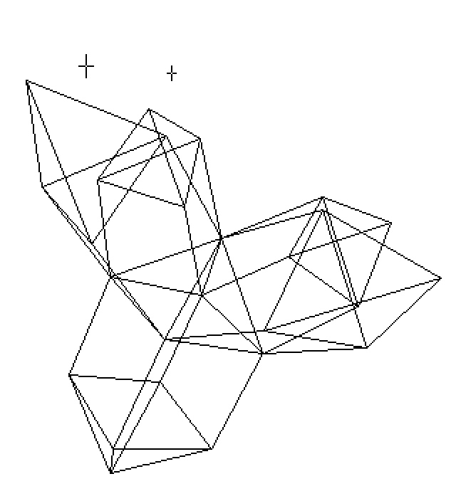
320 x 352 pixels, produced using a Vic-20 computer.This was a much more complex form to enter, with 26 points and 56 lines. The 3D program makes use of an angle of rotation (view), an angle of attitude (how far rotating up or down), and a resulting image rotation angle. I was able to enter how close ‘the viewer’ was to the object and how far from the viewer the projection plane was. Using the high-resolution printing method described above, I was able to print out good high-resolution images of 3-dimensional objects. I also produced images that could be viewed on a home-made 3-dimensional viewer (requiring 2 separate images - one for the left eye and one for the right eye viewed back through front faced mirrors) to create sensational renditions of wire frame objects sitting in wire frame 3-dimensional spaces. The Vic-20 could certainly be used to create some amazing images. |
|
More Details | Home Page Menu / Back to Overview Page
| Prev | Gallery 4 - Vic-20 Graphics - page 6 (of 17) |